Hello,
Is there anything in Pylinac for light to rad testing? I can’t find anything, but I’m wondering if any one of you clever users has figured out a hack. (Or maybe you’re just more observant than I am)
Thanks
Hello,
Is there anything in Pylinac for light to rad testing? I can’t find anything, but I’m wondering if any one of you clever users has figured out a hack. (Or maybe you’re just more observant than I am)
Thanks
There’s no explicit light to rad test in pylinac. This is mostly because I didn’t want an interactive test where you click on film markings for example. In my clinic, I would do light rad when I had my graph paper out for monthly mechanicals. I would line up the jaws to the graph paper to 10x10 according to the light field (I did this twice, one for each bulb per energy tested) and then took an EPID image. Then I analyzed the EPID image profiles using the profile module, comparing the values to the nominal values since I lined up to them w/ the light field.
Could a module ever be made for the FC-2 phantom from Standard Imaging?
Yes, of course. All it takes is images and some elbow grease ![]()
We’re currently trying to work on something where we use the _find_bb() function in the winston lutz module to automatically detect the peripheral BB’s. I need to figure out how to make _find_bb() locate more than one BB though. I think once you did that you could use Profiles to find beam edges.
The solution we have that’s currently running just uses the central BB and draws profiles through there to find the field edges. (ignore the peripheral BBs)
A generic bb-finding algorithm would be a good feature. You guys are finding too many bugs I have to squash first =)
It’s a hack, but you could rework the geometric node-finding algorithm here: https://github.com/jrkerns/pylinac/blob/master/pylinac/ct.py#L394-L406. This finds the geometric nodes of the catphan but is close enough to bb’s its pretty usable as-is; just change the bounds of the search region. It will return the centers of multiple bb-like objects. See the called function get_regions as well.
David, are you writing the module for a specific commercial phantom? Which one?
I was considering trying my hand at writing a module for the RIT L-Rad phantom: https://radimage.com/products/phantoms/#RITLRad
In any case, I assume the work you’re doing right now would be re-usable for other light-rad phantoms. Would be glad to assist in any way I can.
Well, first off, I think calling our code a ‘module’ is giving it way too much justice haha
The code is being written for the SI FC2 (with top plate). Currently it only uses the rudimentary code to find the central BB from the top plate and get field sizes from there. What we’re trying to move towards is detecting multiple objects in the base phantom so that the top plate isn’t needed
Hi David,
Any chance you can share your code on GitHub?
It might be useful since I want to work on something similar.
Marc
If anyone is interested, I’ve had a go at creating a light-rad test using the get_regions() found in ct.py
It’s for a custom phantom that was made in house from a 1cm thick Perspex block with a 15x15cm square outline and tungsten pins inset 1cm from each corner. I think that’s fairly similar to the FC-2 phantom from Standard Imaging, except without the 10x10cm part.
I’ll upload the code and test image I used. My intentions are to use this to create an upload test in QATrack+.
Hopefully someone here finds this useful.
I’m not a coder primarily, so if anyone improves on it please let me know!
Ben
light_rad.py (5.06 KB)
light-rad_image.dcm (3.13 MB)
This is really nice work! I tried it with an image from a Trilogy (I had to invert the image, also the panel is rectangular) with the FC-2. With only a couple of changes, I was able to get it to work! I’m sure changes can be made, but this would be really nice to integrate further.
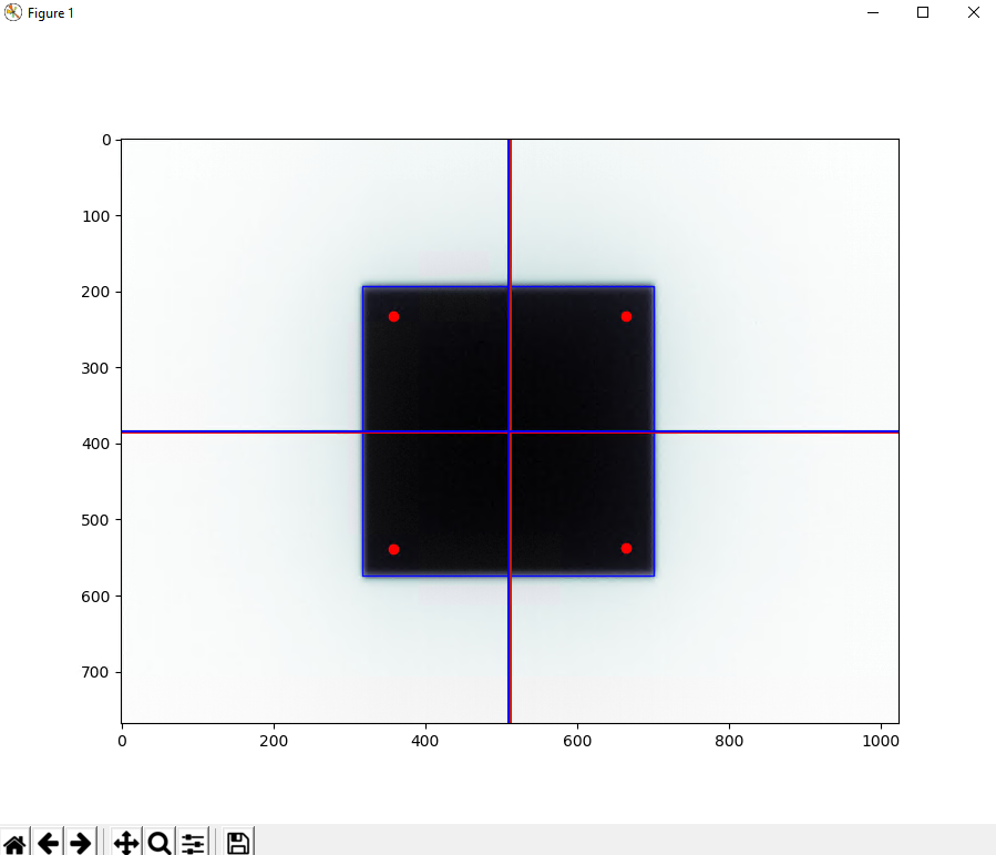
Pixel spacing:0.392
Array size (x):1024 Array size(y):768
Radiation field center (pixels): (508.98, 383.43)
Radiation field size:
Crossplane = 100.26mm
Inplane = 99.76mm
BB Centers:[(357.73, 232.83), (663.47, 231.97), (358.58, 538.61), (664.46, 537.87)]
Light field center (pixels): (511.06, 385.32)
Light-Rad difference:
Crossplane = 0.54mm
Inplane = 0.49mm
LVR.py (5.35 KB)
Glad you found it useful!
It’s better that you did array shape for both x and y, makes it more robust to image shapes other than square.
I like the BB sactter plot too, I was going to add that but I probably would have ended up doing it a long way around; your one-liner of scatter(*zip(*centers), c=‘red’) is much nicer.
Again, with robustness in mind, perhaps there is a clever way to automatically detect if the image needs inverting first?
Did you happen to try a 15x15cm field on your FC-2? I assume for that case you would see all 8 BB’s? I’m not sure how it would work but possibly you may only need to change the lines for regionprops, x_bb and y_bb to range(8). Could even have an if else statement for the case of 4 and 8 BB’s.
I’m interested to see how you get on with it.
Ben
Using a 15x15 field on the FC-2 is also possible. Searching for the other BBs is a great idea. I was wondering if the outer 8 could be one array of points, and the inner BB could be included as a separate point (the central BB on the FC-2 is on an upper plate aligned to the crosshair light field, the outer 4 or 8 are aligned to the jaw light field using the bottom plate). Here is a check to invert the image if that is an issue (it did invert the image on our Truebeam in service mode).
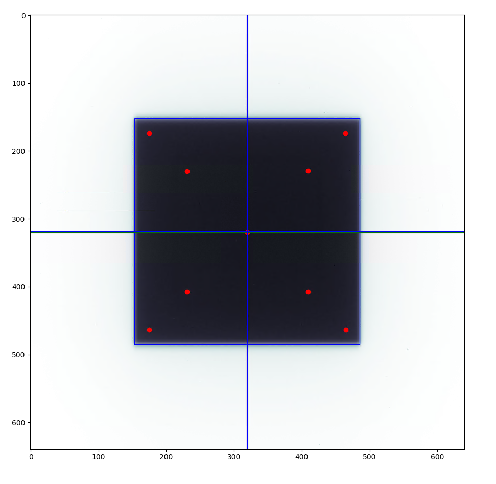
SID: 1500.0
Pixel spacing at SID:0.672
Array size (x):640 Array size(y):640
Radiation field center (pixels): (319.5, 318.95)
Radiation field size:
Crossplane = 14.882 cm
Inplane = 14.961000000000002 cm
Num ROI:9
Outer BBs:[(174.81, 174.92), (230.37, 230.19), (463.32, 174.06), (408.11, 229.64), (319.84, 319.04), (230.96, 407.8), (175.85, 463.27), (408.65, 407.21), (463.8, 462.55)]
Central BB:[(319.78, 319.0)]
Light field center (pixels): (319.52, 318.74)
Light-Rad difference:
X/Y: 0.13 / 0.02 mm
Left/Right: -0.46 / -0.72 mm
Top/Bottom: -0.17 / -0.22 mm
LVR.py (8.22 KB)
Would anyone be able to test this out with their images and see how it works? I have a testpack if anyone wants it for QAT+, or we could share it with that group also.
I’m using it successfully in QATrack+ now with an upload test and displays the image plot too. It pretty much agrees exactly with the test macros I’ve been using in ImageJ. Differences possibly being down to pylinac profile module is able to use interpolation; something not built in to our ImageJ macro.
I think you’re right, Landon, you should post it in QATrack+ groups and hopefully get more people to test it. Maybe we could have it integrated into pylinac itself (with Mr Kerns blessing)
Hi Ben,
That’s great. Thank you. I tested it on my EPID image and it works properly. So, how can we use this code for digitized films (like Tiff or something else image format)?
Best Regards,
Glad it’s working for you. I’ve not attemted to use it on scanned films and I suppose it depends on if your film image also has a similar arrangement of BB markers on it. If so, it shouldn’t be too much different except you’d have to turn your TIFF into a 2D array using PIL (See this answer on Stackexchange). If you are using the code I uploaded previously would reccomend changing the lines about #Get central row/col for the line profile, to;
array_size_x = arr_img.shape[1]
array_size_y = arr_img.shape[0]
print(f’Array size (x):{array_size_x} Array size(y):{array_size_y}')
mid_array_x = int(array_size_x/2)
mid_array_y = int(array_size_y/2)
#Detect if the image needs inverting by checking pixel value of center vs corner.
if (arr_img[mid_array_x, mid_array_y] <= arr_img[0,0]):
arr_img.invert()
This will be more robust to non-square images and detect if inversion is needed (Thanks Landon).
Of course you will also have to change the value for px_spac_corrected to be the correct pixel spacing per mm for your scanner.
I hope any of that is useful.
Ben
I’ve recently made some changes. I’ve added some code to calculate the angle of rotation of the light field, based on angles between located BBs; and the angle of rotation of the radiation field, based on angles between some additional off-center field edges. There’s also a pre-made dictionary of results and .png image to return to QATrack+ for those that use it.
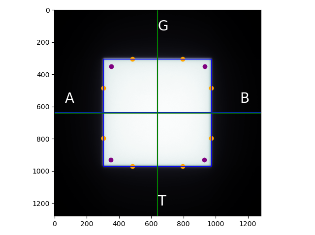
Array size (x):1280 Array size(y):1280
Radiation field center (pixels): (638.11, 637.56)
Radiation field size:
Crossplane = 150.11mm
Inplane = 149.25mm
Light field center (pixels): (640.84, 640.72)
Light-Rad difference:
Crossplane = -0.61mm
Inplane = -0.71mm
Lightfield Rotation = 0.141 degrees
Radiation Field Rotation = 0.095 degrees
Light-Rad_Angle.py (10.4 KB)
This looks great! The rotations are nice to have reporting to QAT+. Do you also report any asymmetric jaw differences?
I’m not currently reporting asymmetric jaw sizes with this test since we do other QC that can detect that, but I do still think it would be good to include at some point. I did think about calculating asymmetric jaws size but I don’t think it can be done reliably without an FC-2 style top plate to mark the CAX point to measure from. I like your modification that works for the FC-2 with top plate, so perhaps I can make my own top plate too in the future.
Ben